Doświadczenie w gięciu blach
A: Tonnage ion of bending machine
During the bending process, the force between the upper and lower dies is applied to the material, causing the material to plastically deform. Working tonnage refers to the bending pressure during bending. The influencing factors for determining the working tonnage are: bending radius, bending method, mold ratio, elbow length, thickness and strength of bending material, etc.
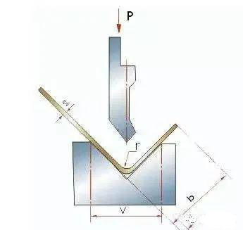
Generally, the working tonnage can be ed according to the following table and set in the processing parameters.
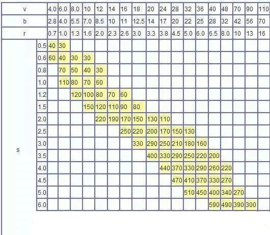
1. The value in the table is the bending pressure when the sheet length is one meter:
Example: S = 4mm L = 1000mm V = 32mm
Look up the table and get P = 330kN
2. Tabela ta jest obliczana na podstawie materiału o wytrzymałości σb = 450 N / mm2. Podczas gięcia innych materiałów nacisk na gięcie jest iloczynem danych w tabeli i następujących współczynników;
Brąz (miękki): 0,5;
Stal nierdzewna: 1,5;
Aluminium (miękkie): 0,5;
Stal chromowo-molibdenowa: 2,0.
3. Przybliżona formuła obliczeniowa ciśnienia zginającego
P = 650s2L / 1000v
P —— kn
S —— mm
L —— mm
V —— mm
Tabela porównawcza ciśnienia zginającego
B. Często spotykane problemy podczas gięcia blachy
1) Powszechnie stosowane matryce do gięcia
Powszechnie stosowana forma do gięcia, jak pokazano poniżej. Aby przedłużyć żywotność formy, części są projektowane z zaokrąglonymi narożnikami w jak największym stopniu.
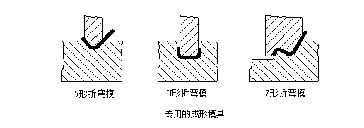
Jeśli wysokość kołnierza jest zbyt mała, nawet użycie matrycy do gięcia nie sprzyja formowaniu. Ogólnie wysokość kołnierza L≥3t (w tym grubość ścianki).
Krokowa metoda przetwarzania
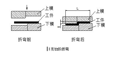
W przypadku niektórych niskoprofilowych gięć krokowych w kształcie litery Z, producenci przetwarzający często używają prostych form do stempli lub pras hydraulicznych, a małe partie mogą być również przetwarzane na maszynie do gięcia za pomocą matrycy stopniowanej, jak pokazano na poniższym rysunku. Jednak wysokość H nie powinna być zbyt wysoka, ogólnie powinna wynosić (0 ~ 1,0) t, jeśli wysokość wynosi (1,0 ~ 4,0) t, należy rozważyć zastosowanie formy formy struktury dodawania i odprowadzania zgodnie z do rzeczywistych warunków.
Wysokość tego etapu formy można regulować poprzez dodanie podkładek, więc wysokość H można regulować dowolnie, ale jest też wada, że długość L nie jest łatwa do zagwarantowania, a pionowość boku pionowego nie jest łatwa gwarancja. Jeśli wysokość H jest duża, należy rozważyć zgięcie na giętarce.
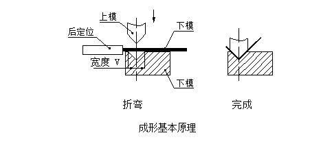
Istnieją dwa rodzaje giętarek: zwykła giętarka i giętarka CNC. Ze względu na wysoką precyzję i nieregularne kształty gięcia, gięcie blach urządzeń komunikacyjnych jest zwykle gięte za pomocą giętarki CNC. Podstawową zasadą jest użycie noża do gięcia (górna matryca) i rowka w kształcie litery V (dolna) giętarki. Die), gięcie i formowanie części blaszanych.
Zalety: wygodne zaciskanie, dokładne pozycjonowanie i duża prędkość przetwarzania;
Wady: niskie ciśnienie, może przetwarzać tylko proste formowanie i niska wydajność.
Podstawowe zasady formowania
Podstawową zasadę formowania pokazano na poniższym rysunku:
Nóż do gięcia (górna matryca)
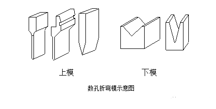
Formę noża do gięcia pokazano na poniższym rysunku. Podczas obróbki jest głównie edytowany zgodnie z kształtem przedmiotu obrabianego. Zasadniczo istnieje wiele kształtów noży do gięcia producentów przetwórczych, szczególnie tych o wysokim stopniu specjalizacji. Aby przetwarzać różne złożone gięcia, noże do gięcia o wielu kształtach i specyfikacjach są dostosowane.
Dolna matryca zwykle wykorzystuje matrycę V = 6t (t to grubość materiału).
Istnieje wiele czynników, które wpływają na proces gięcia, w tym głównie promień górnego łuku matrycy, materiał, grubość materiału, niższa wytrzymałość matrycy, rozmiar dolnej matrycy i inne czynniki. Aby zaspokoić potrzeby produktu, producent zserializował już formę noża do gięcia pod warunkiem zapewnienia bezpieczeństwa giętarki. Musimy mieć ogólne zrozumienie istniejącej formy noża do gięcia podczas projektowania konstrukcji. Patrz rysunek poniżej, górna kostka znajduje się po lewej stronie, a dolna kostka jest po prawej stronie.
Podstawowe zasady sekwencji obróbki gięcia:
(1) Gięcie od wewnątrz na zewnątrz;
(2) Gięcie od małego do dużego;
(3) Wygnij najpierw kształt specjalny, a następnie zgnij kształt ogólny;
(4) Po utworzeniu poprzedniego procesu nie wpływa on ani nie zakłóca następnego procesu.
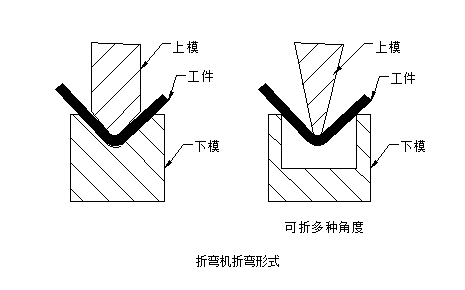
The current bending form is generally shown in the following figure:
2) Bending radius
When bending sheet metal, a bending radius is required at the bending place. The bending radius should not be too large or too small, and should be ed appropriately. If the bending radius is too small, it is easy to cause cracking at the bending point, and if the bending radius is too large, the bending is easy to rebound. The preferred bending radius (inner bending radius) of various materials with different thicknesses is shown in the table below
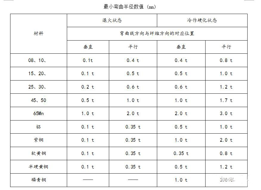
The data in the table above is the preferred data, for reference only. In fact, the corners of manufacturers' bending knives are usually 0.3, and a small number of bending knives are 0.5.
For ordinary low-carbon steel plate, rust-proof aluminum plate, brass plate, copper plate, etc., the inner fillet 0.2 is no problem, but for some high-carbon steel, hard aluminum, super hard aluminum, this bending round It will cause bending breakage or cracking of the outer corners.
3) Bending and rebound
Springback angle Δα = b-a
Where b——the actual angle of the part after rebound;
a—The angle of the mold.
The size of the rebound angle
See the table below for the springback angle when a single angle is 90 ° free bending.
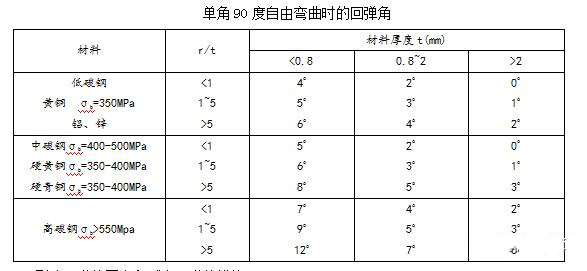
Factors affecting rebound and measures to reduce rebound
① The mechanical properties of the material The rebound angle is directly proportional to the yield point of the material and inversely proportional to the elastic modulus E. For sheet metal parts with high accuracy requirements, in order to reduce springback, the material should be ed as low-carbon steel as possible, not high-carbon steel and stainless steel.
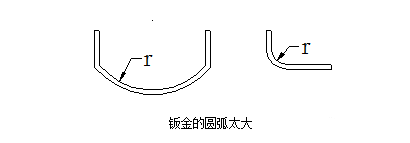
② The larger the relative bending radius r / t, the smaller the degree of deformation and the greater the rebound angle Δα. This is a relatively important concept. The rounded corners of sheet metal bending should be as small as possible, as long as the material properties allow, to improve accuracy. In particular, pay attention to avoid designing large arcs as much as possible, as shown in the following figure, such large arcs have greater difficulty in production and quality control:
4) Calculation of the minimum bending edge in one bending
The initial state of the L-shaped bend at the time of bending is shown below:
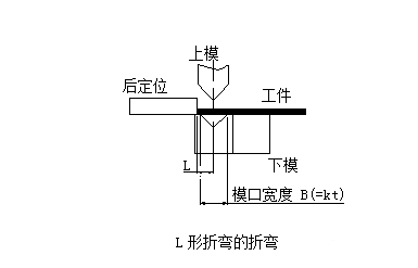
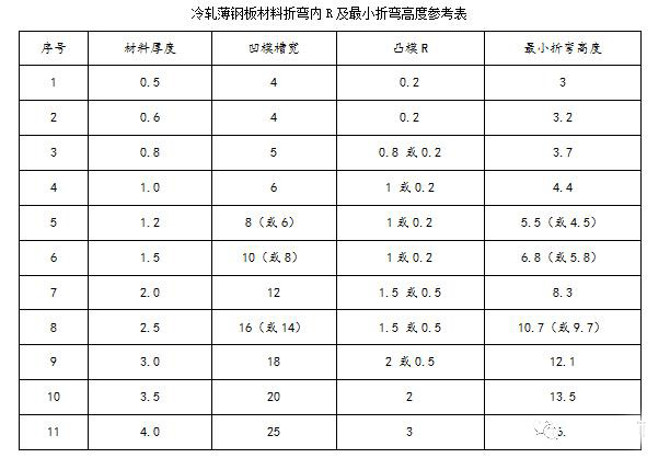
The initial state of the Z-shaped bending at the time of bending is shown in the figure below
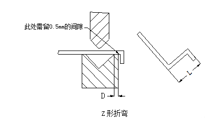
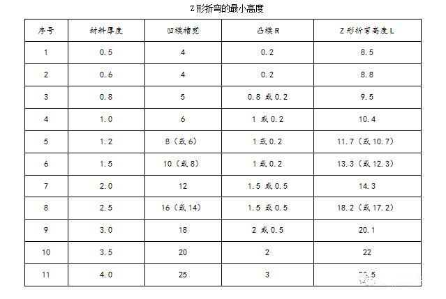
The minimum bending dimension L corresponding to the Z-bending of sheet metal with different material thickness is shown in the following table:
C. Fast calculation method of sheet metal bending and unfolding
When the sheet metal bending and flattening, one side of the material will be elongated and one side will be compressed. The factors affected are: material type, material thickness, material heat treatment and processing bending angle.
Expand calculation principle:
1) During the bending process, the outer layer is subjected to tensile stress and the inner layer is subjected to compressive stress. Between tension and compression, there is a transition layer that is neither tensile nor compressive, called the neutral layer; the neutral layer is bent during the bending process The length is the same as before bending, so the neutral layer is the benchmark for calculating the unfolded length of the bending piece.
2) The position of the neutral layer is related to the degree of deformation. When the bending radius is large and the bending angle is small, the degree of deformation is small. The position of the neutral layer is close to the center of the sheet thickness; when the bending radius becomes small, the bending angle increases When it is large, the degree of deformation increases accordingly, and the position of the neutral layer gradually moves to the inside of the bending center. The distance from the neutral layer to the inside of the sheet is expressed by λ.
On the other hand, with the emergence and popularization of computer technology, in order to make better use of the computer's super analysis and calculation capabilities, people increasingly use computer-aided design, but when computer programs simulate the bending of sheet metal Or it needs a calculation method in order to accurately simulate the process.
Although only to complete a certain calculation, each store can customize a specific program according to its original pinch rules, but nowadays, most commercial CAD and three-dimensional solid modeling systems have provided more general and Powerful solution.
W większości przypadków to oprogramowanie aplikacyjne może być również zgodne z oryginalnymi regułami opartymi na doświadczeniu i szczypcami palców, a także umożliwiać dostosowanie określonej zawartości wejściowej do procesu obliczania. SolidWorks naturalnie stał się liderem w dostarczaniu tej możliwości projektowania blach.

